
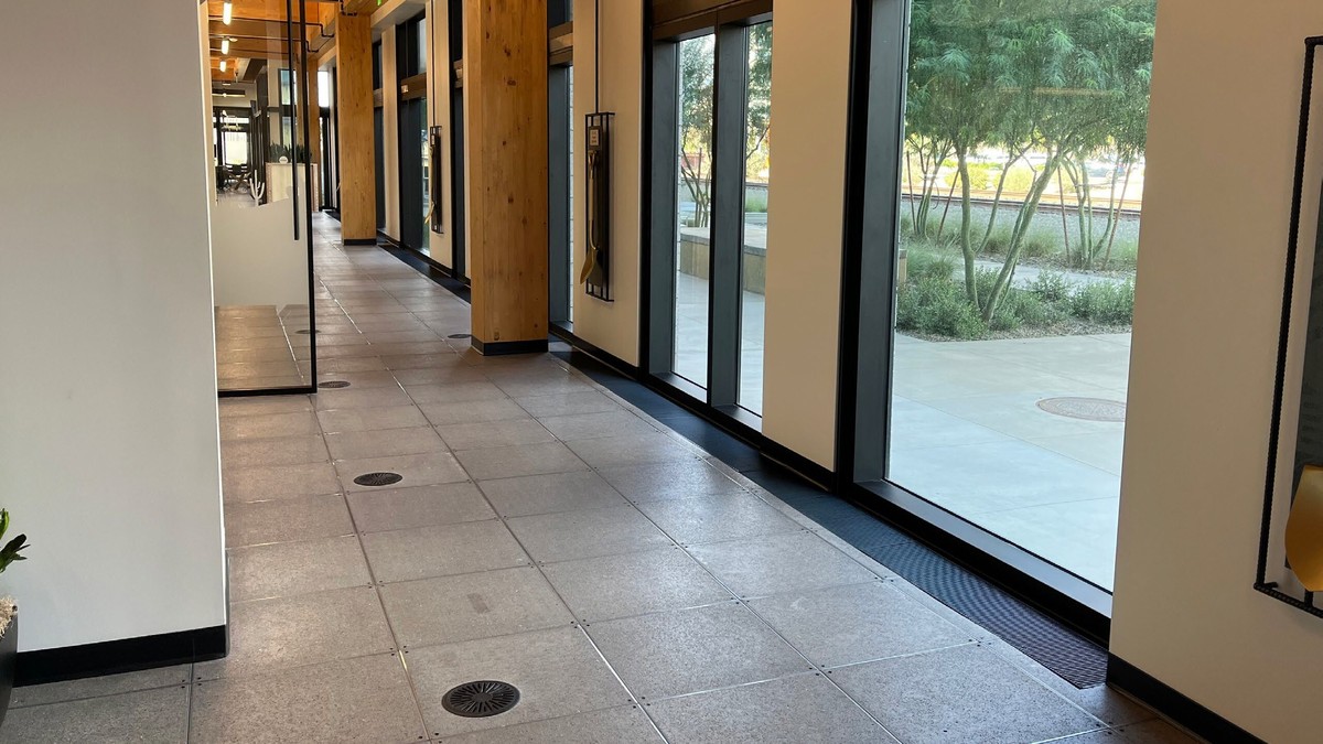
Conventionally air from supply system is provided to room through ceiling diffusers. These diffusers are located at ceiling level say at 10 feet height. Seating position of the occupants is within 4 feet level from ground. Air which is required at this lower level need to cover this 6 feet distance before entering in to comfortable zone. Conditions of air change while dropping down. It gets mixed up with room air close to ceiling. Air at that level is at higher temperature due to lighting heat load. Due to these reasons temperature of the air supplied through ceiling diffusers in conventional overhead supply systems is kept low enough to remain within comfortable range even after mixing with upper level air of the room. Moreover velocity is high enough to cover distance up to seating level. If velocity is low, air will simply diffuse at ceiling level and will not be able to reach comfort zone.
Substantial energy savings may be achieved, if we somehow supply air directly to the comfort zone. This system is called as under floor air distribution system. High temperature air provides same level of cooling as provided by conventional system. High temperature means chillers can be operated at higher set points. Operating chiller at higher outlet temperature saves chiller energy. Savings up to forty percent can be achieved by utilizing this system.
Volume flow of air also reduces with this system. Occupied zone height is reduced. Instead of 10 feet height, air is stratified up to 5 feet height.
For same air changes, volume of air reduces due to reduced height. Less air volume means fan power is reduced. It saves air transportation energy required to recirculate air. Small capacity fan motors are required. When under floor open plenums are used, instead of ducted supply, static resistance drops. Less resistance to air flow means less power required to move air. This also saves fan energy. Room thermostat set point is kept higher than for overhead system. Location of supply diffusers is coordinated with interior layout. When position of furniture is changed or new interior items are added, air devices positions are adjusted accordingly. Special care is required for air outlet locations, as wrong position may cause discomfort to occupants.
Leave a comment
« Part Load Performance of Screw Compressors
Recent Posts
- Multipurpose Hall Environment Control
- Piping Network Considerations for Air Conditioning System
- Fan Energy Saving Systems for Space Conditioning
- Air Handling Unit Heat Transfer Capacity
- Green Pumping Solutions
- Using Ceiling Space for Return Air Path
- Managing Night Time and Holiday Loads
- Considerations for Services Openings in High Rise Buildings
- Selecting Air Handling Unit Fan
- Mitigation of Plant Room Noise Transmission
- Frictionless Chillers
- Under Floor Air Distribution Systems
- Part Load Performance of Screw Compressors
- Frost Control of Evaporator Coil
- How to Achieve Low Humidity Conditions with Minimum Energy Consumption
Categories
- AHU Coils
- Air Conditioning Systems
- Air Distribution
- Air Filtration
- Air Handling Units
- Building Management System
- Chilled Water Plant ΔT
- Chiller Plant Control Sequence
- Chillers
- Combined Cooling Heating & Power Systems
- Cooling Towers
- Cost Effective and Energy Efficient Air Side Economizer Systems
- Data Center Air Conditioning
- Demand Control Ventilation
- Displacement Ventilation Systems
- Ducting System
- Energy Efficient Pumping
- Energy Recoveries
- Fans For High Performing HVAC
- Green Building Design
- Green Solution
- Hospital HVAC
- How to Control Low Chilled Water delta-T
- Indoor Air Quality
- Insulations
- Kitchen Ventilation
- Night Time Precooling
- Noise Control
- Optimized Chiller Operation
- Pumping Solutions
- Refrigerant Pipng
- Smoke Management Systems
- Solar Energy Systems
- Thermal Energy Storage for Cooling
- Variable Frequency Drives
- Variable-Flow Pumping Systems
Archives
| M | T | W | T | F | S | S |
|---|---|---|---|---|---|---|
| « Feb | ||||||
| 1 | 2 | 3 | 4 | 5 | 6 | |
| 7 | 8 | 9 | 10 | 11 | 12 | 13 |
| 14 | 15 | 16 | 17 | 18 | 19 | 20 |
| 21 | 22 | 23 | 24 | 25 | 26 | 27 |
| 28 | 29 | 30 | 31 | |||
Recent Comments
- admin on Air Conditioning Duct Designing For Minimum Losses
- payday advance loan idaho on Air Handling Unit Heat Transfer Capacity
- Air Pollution Indoors on Air Conditioning Duct Designing For Minimum Losses
- Maxine Catalli on Air Conditioning Duct Designing For Minimum Losses
- Lakendra Krokus on How to Reduce Makeup Air Requirement for Kitchen Ventilation
Meta
- Log in
- Entries RSS
- Comments RSS
- WordPress.org